IoT Driving Tracker
An ESP32-based vehicle telemetry system that automatically detects journeys using GPS and accelerometer data, logs trips to an SD card, uploads over Wi-Fi, and lets you review routes and driving behaviour through a web dashboard.
ESP32 · Neo-6M GPS · LIS3DH · SD card · Arduino/C++ · HTTP
What it does
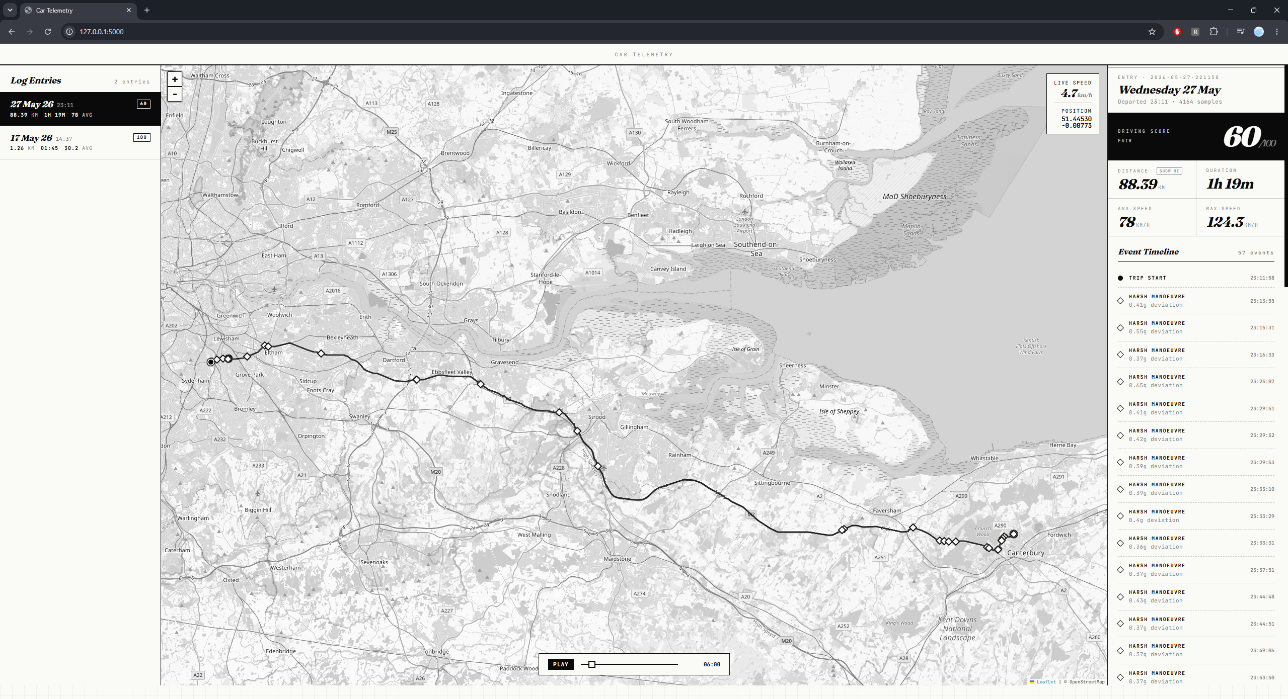
You put the device in the car, power it on with a USB power bank, and it handles everything else. When the vehicle starts moving, the GPS and accelerometer detect it and trip recording begins automatically. Location, speed, altitude, and acceleration are logged continuously. When the car stops, the trip is finalised and saved. The next time the device is near a known Wi-Fi network, it uploads the completed trip to a server where you can review your routes and driving behaviour through a web dashboard.
The whole thing runs on around £15 of commodity hardware. Commercial OBD-II trackers do something similar for £50 to £200 and lock your data into proprietary platforms.
Hardware
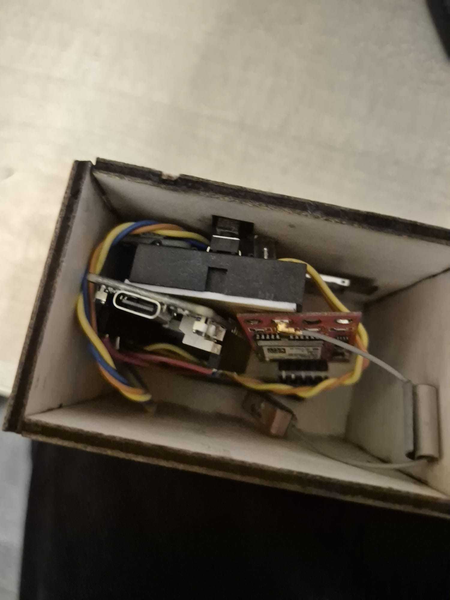
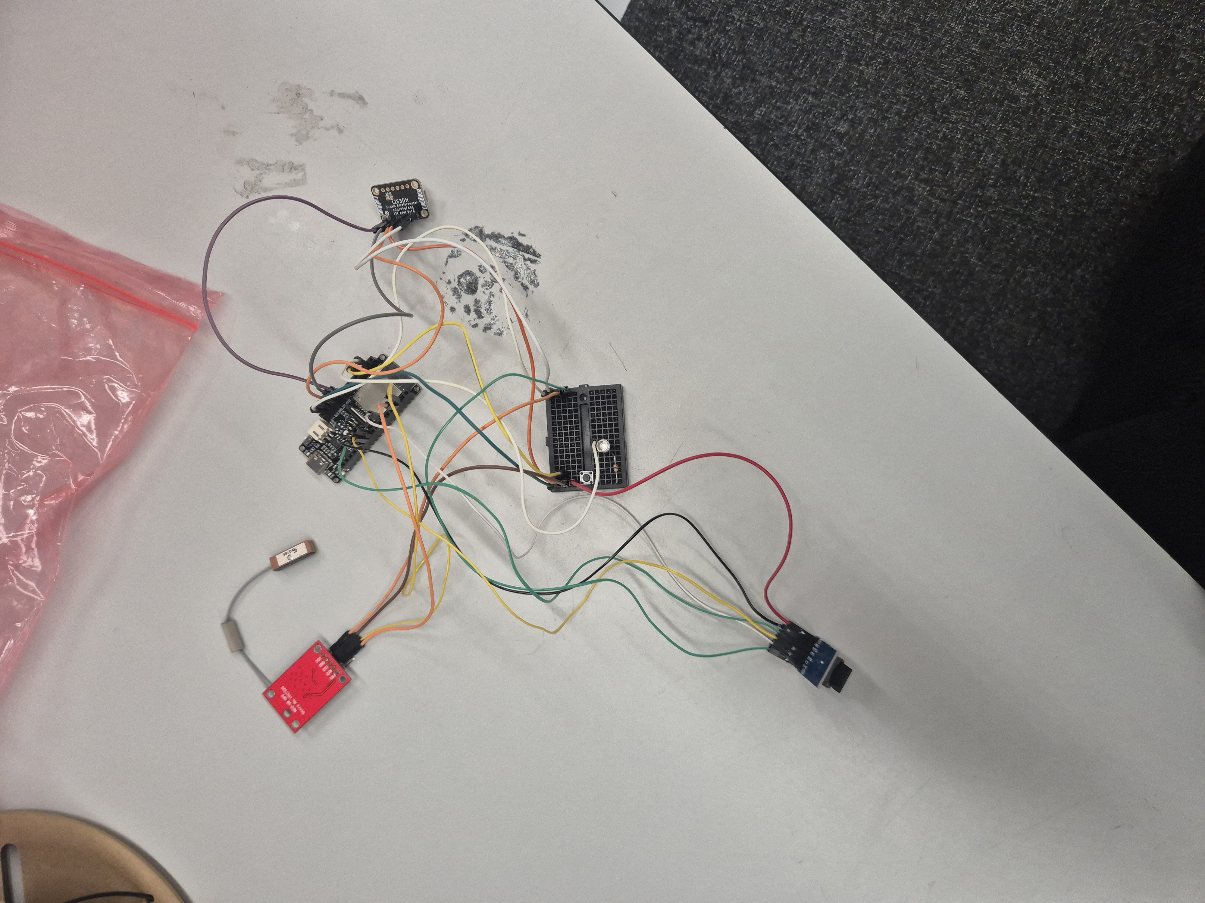
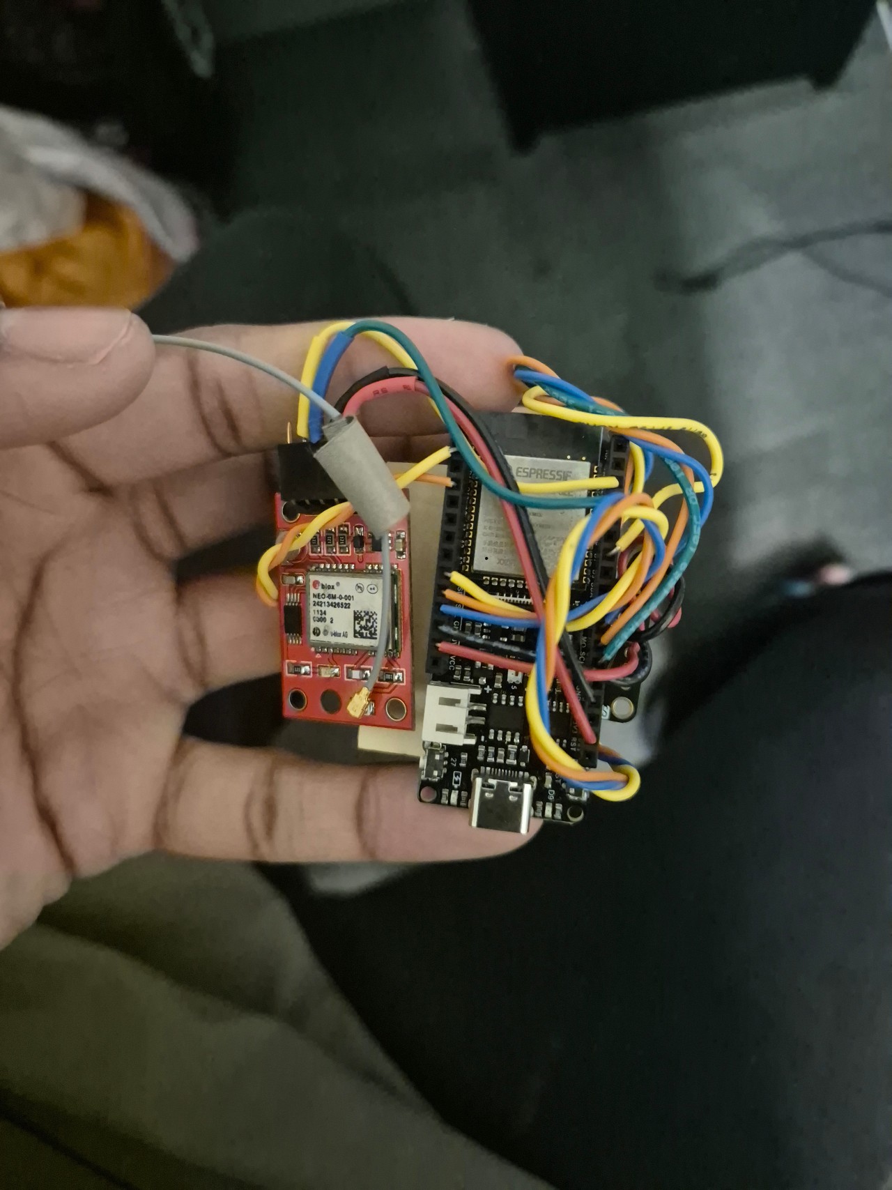
Four components: an ESP32 as the central controller, a NEO-6M GPS module communicating over UART for location and speed, a LIS3DH accelerometer over I2C for movement detection, and a microSD card module for local storage. The ESP32 coordinates all of them and handles the Wi-Fi connection for uploads.
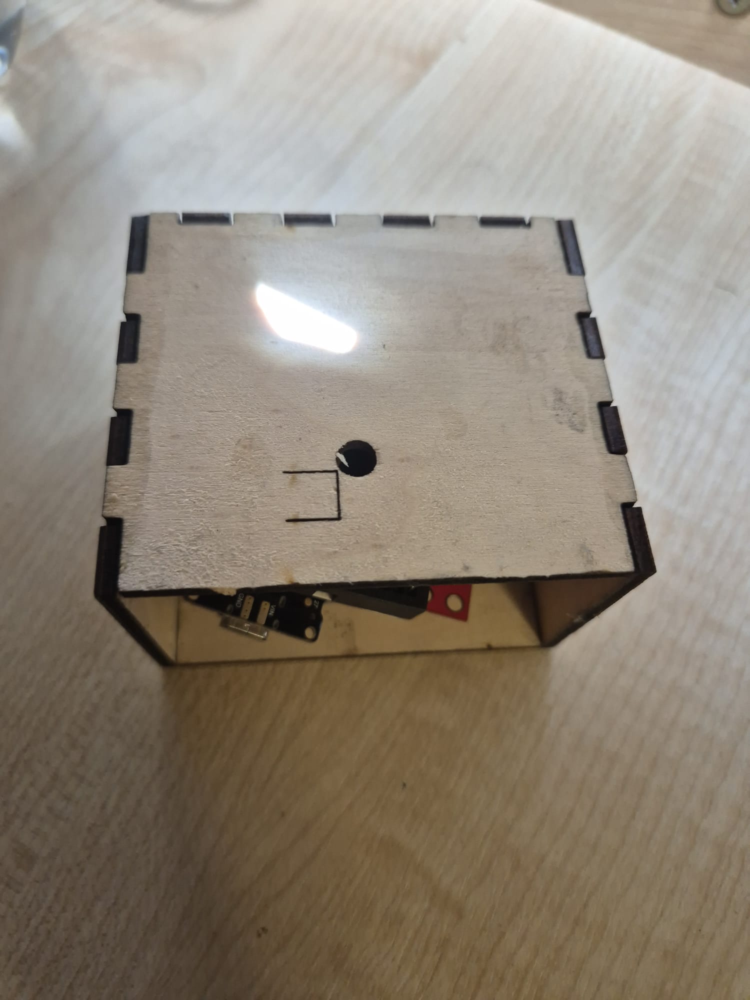
Power comes from a USB power bank rather than the car's 12V supply, which would need a separate regulator. It is simple and it works.
Trip detection
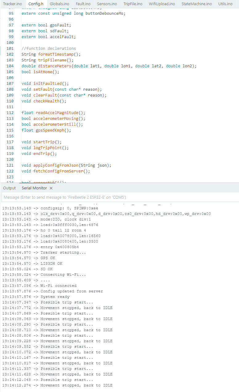
Journey detection runs on a finite state machine with states for idle, moving candidate, trip active, stopped candidate, trip ended, uploading, and sleeping. The state machine approach prevents false recordings from brief movement or GPS drift. A trip starts when GPS speed exceeds a configurable threshold, or sustained accelerometer movement is detected, and that condition must hold for a confirmation window before the system commits to an active trip. Trip end works the same way in reverse.
Logging and upload
During an active trip, telemetry is written to the SD card periodically in CSV format: timestamp, latitude, longitude, GPS speed, altitude, satellite count, and accelerometer G reading. Local storage means no data is lost if the network is unavailable. When a trip ends and the device is near a configured home zone, it connects to Wi-Fi over HTTP and uploads the file. Trips stay on the card if the upload fails and retry on the next connection. Remote configuration is also pulled from the server, so operational parameters can be changed without reflashing the firmware.
Power and reliability
When no trip is active the device enters deep sleep to conserve battery. Wi-Fi is only enabled during uploads. The hardware connections for accelerometer interrupt-based wakeup and GPS power mode switching are in place as future work. A fault LED alerts to problems that would otherwise be invisible: GPS fix failures, SD card errors, and failed uploads, without needing serial debug access.